2026 · Personal project · Mechanical design
Torque actuator
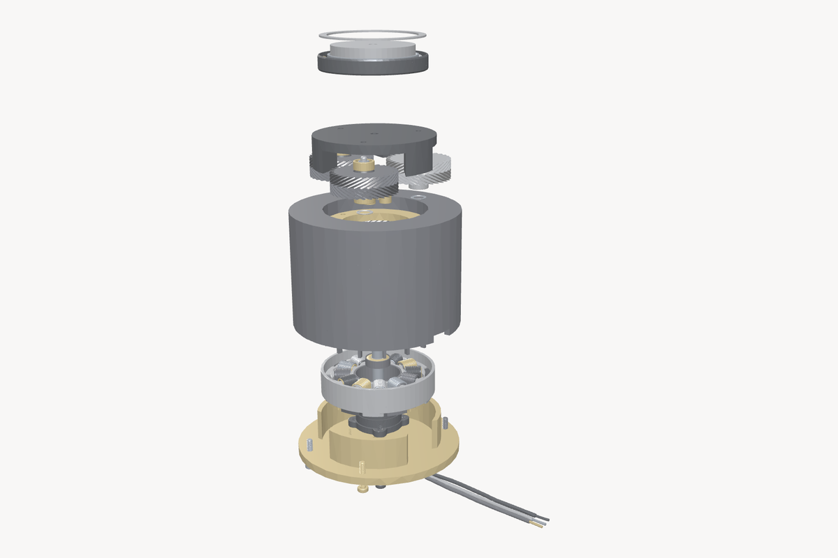
A quasi‑direct‑drive joint for small legged robots. One 6:1 planetary stage multiplies the motor’s torque while keeping it backdrivable, and double‑helical teeth cancel the axial thrust a single helix would push into the bearings.
Inspect
Take it apart yourself
The real V5 export from CAD, yours to turn. Drag to orbit, pull the slider, snap to a standard view.
Every part is its own body, so separation pulls the assembly apart along the output axis: the cap, the carrier and its three double‑helical planets, the housing, the stator, and the base.
Why 6:1
Legged robots need joints you can push back on. A low ratio keeps the motor backdrivable, so the leg gives a little when it lands and motor current can stand in for a torque sensor. That is why quasi‑direct‑drive actuators tend to settle on a single stage around 6:1.
What the numbers say
Output torque is motor torque times the ratio: 0.37 Nm × 6 is about 2.2 Nm continuous, and about 3 Nm at a 20 A peak. Gear losses take a few percent off that. These are calculated, not measured, and the motor is the limit, not the gearbox.
Where it stands, honestly. This is a design study. Five revisions in CAD and the calculations are as far as this one goes for now. It is here because the thinking is worth keeping.